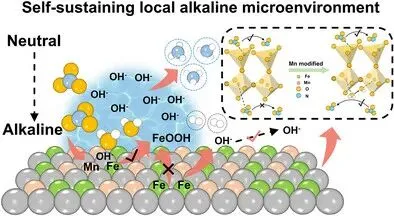
图1 (a) 1D MnFeOₓ合成过程示意图;(b) 场发射SEM图像;(c,d) HRTEM及HRTEM-EDS元素映射图像;(e) 1D MnFeOₓ与1D FeOₓ的拉曼光谱;(f) Fe 2p XPS谱图;(g) Fe K边归一化XANES谱图(以标准Fe箔为参考)
Figure 1 (a) Schematic illustration for the synthetic process of 1D MnFeOₓ. (b) Field-emission SEM image of 1D MnFeOₓ. (c,d) HRTEM and the HRTEM-EDS elemental mapping images of 1D MnFeOₓ. (e) Raman spectra of the 1D MnFeOₓ and 1D FeOₓ. (f) Fe 2p XPS spectra of 1D MnFeOₓ and 1D FeOₓ. (g) Normalized XANES spectra at the Fe K edge for 1D MnFeOₓ and 1D FeOₓ, with standardized Fe foil as references.
图1 系统展示了1D MnFeOₓ催化剂的结构特征与电子态调控。通过静电纺丝与可控煅烧成功制备出均匀、非团聚的一维纳米纤维,其由相互连接的纳米立方体构成,形成多孔网络结构,有利于反应物扩散与活性位点暴露。EDS mapping证实Mn、Fe、O元素沿纤维轴向均匀分布。拉曼光谱显示Mn掺杂诱导Fe-O-Mn桥接结构形成,引起键长畸变与电荷重排。XPS与XANES结果共同证明:Mn的引入使Fe的电子密度向Mn转移,Fe氧化态升高,且Mn优先占据八面体位点,保留四面体Fe活性中心,为后续动态碱性微环境的构建奠定结构基础。
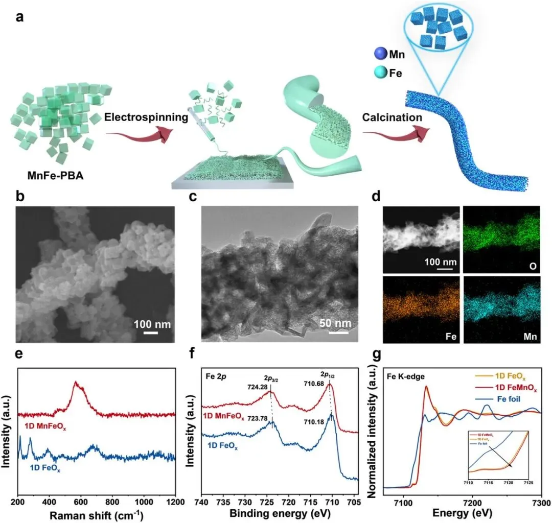
图2 (a) 1D MnFeOₓ在含/不含0.05 M KNO₃的0.5 M K₂SO₄电解液中的LSV曲线;(b) 不同电位下1D MnFeOₓ的NH₃法拉第效率;(c) NH₃产率与法拉第效率随电位变化;(d,e) 不同催化剂在各电位下的FE与产率对比;(f) 使用K¹⁴NO₃与K¹⁵NO₃进行NO₃⁻RR后的¹H NMR谱图;(g) 在−0.9 V vs. RHE下连续10次循环测试的电流密度与FE稳定性;(h) 本工作与近期报道的中性介质铁基催化剂性能对比Figure 2 (a) LSV curves of 1D MnFeOₓ in 0.5 M K₂SO₄ electrolyte with and without 0.05 M KNO₃. (b) FE values of 1D MnFeOₓ at each given potential. (c) NH₃ yield rate and FEs of 1D MnFeOₓ. (d) Comparison of FE for different catalysts at each given potential. (e) Comparison of NH₃ yield rate for different catalysts at each given potential. (f) ¹H NMR spectra of electrolytes after NO₃⁻RR using K¹⁴NO₃ and K¹⁵NO₃. (g) Evaluation of current density and FE during ten consecutive cyclic tests for the electrochemical NO₃⁻RR to NH₃ at −0.9 V versus RHE in a 0.5 M K₂SO₄ electrolyte containing 0.05 M KNO₃. (h) FE(%), NH₃ selectivity(%), and NH₃ yield rate(mg h⁻¹ cm⁻²), and current density(mA cm⁻²), and potential(V vs. RHE) of 1D MnFeOₓ in this work compared with recently reported iron-based electrocatalysts in neutral media for NO₃⁻RR activity.
图2 全面评估了1D MnFeOₓ在中性条件下的NO₃⁻RR性能。LSV曲线确认硝酸根还原电流显著增强。在−1.0 V vs. RHE时,NH₃法拉第效率高达95.9%,产率达12.3 mg h⁻¹ cm⁻²,远超对照样品1D FeOₓ及其他文献催化剂。¹⁵N同位素标记实验通过NMR双重峰(6.96 & 6.82 ppm)确证产物NH₃完全来源于NO₃⁻还原。稳定性测试表明催化剂在10轮循环后性能无衰减。性能雷达图显示该催化剂在中性介质铁基材料中处于领先地位,凸显其优异活性、选择性与实用性。
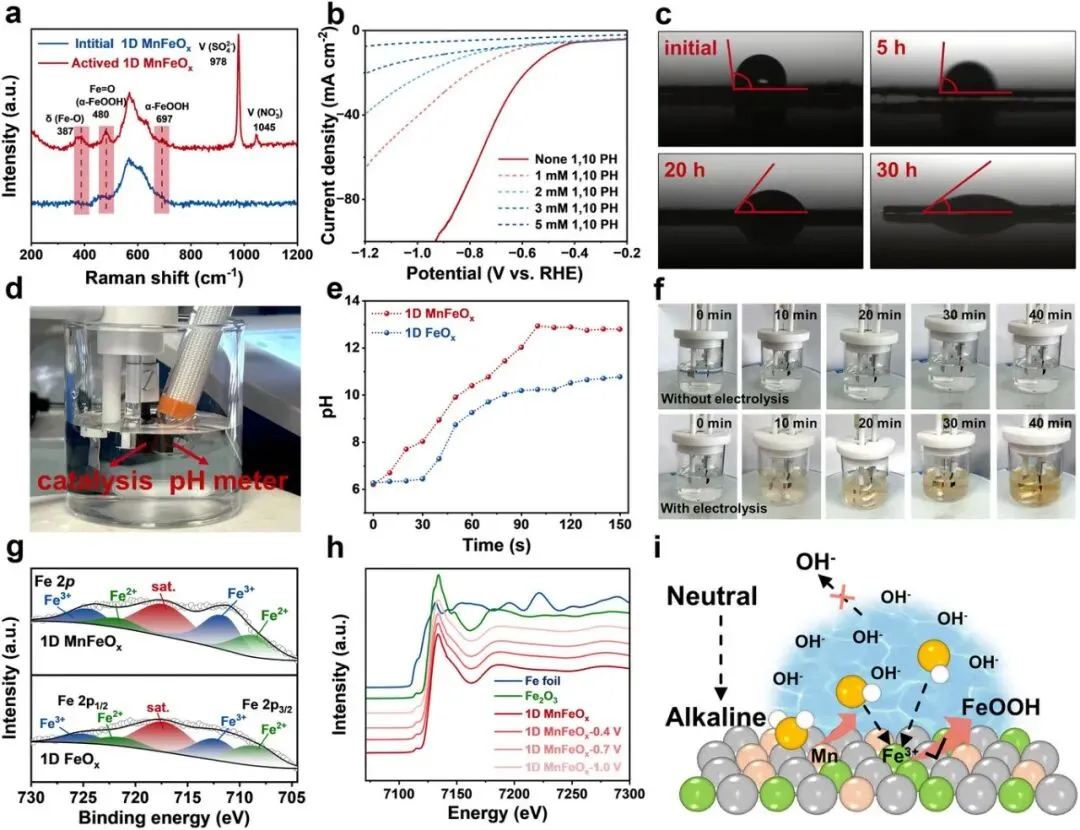
图3 (a) 初始与活化后1D MnFeOₓ的拉曼光谱;(b) 添加不同浓度1,10-菲啰啉清除剂后的LSV曲线;(c) 不同电解时长下1D MnFeOₓ的接触角测量;(d) 原位pH测量装置照片;(e) 1D MnFeOₓ与1D FeOₓ表面pH随反应时间变化;(f) 含3 mM 1,10-PH电解液在电解/非电解条件下的颜色演变;(g) −0.9 V vs. RHE电解5小时后的高分辨Fe 2p XPS谱图;(h) 不同电位下的原位XANES谱图;(i) 阴极表面自维持局部碱性生成机理示意图
Figure 3 (a) The Raman spectra of initial and activated 1D MnFeOₓ. (b) LSV curves of 1D MnFeOₓ in a solution containing 0.5 M K₂SO₄ and 0.05 M KNO₃ with varying concentrations of 1,10-phenanthroline(1,10-PH) as a scavenger. (c) Contact angle measurements of 1D MnFeOₓ with different electrolysis durations. (d) Photograph of in situ pH measurement using a pH meter. (e) The pH as a function of reaction time at 1D MnFeOₓ and 1D FeOₓ surfaces using the pH meter method. (f) Color evolution of the 0.5 M K₂SO₄ electrolyte(containing 0.05 M KNO₃ and 3 mM 1,10-PH). Up: under electrolysis conditions; down: under non-electrolysis conditions. (g) High-resolution Fe 2p XPS spectra of the 1D MnFeOₓ and the 1D FeOₓ catalyst at −0.9 V versus RHE for 5 h. (h) In situ XANES spectra of 1D MnFeOₓ at different potentials. (i) Schematic diagram of self-sustaining local alkalinity generation at the 1D MnFeOₓ cathode surface.
图3 深入揭示了“自维持碱性微环境”的形成机制。拉曼与接触角数据表明,电解过程中1D MnFeOₓ表面动态生成亲水性α-FeOOH,使接触角显著下降,而1D FeOₓ无此现象。加入Fe²⁺清除剂1,10-PH后,电流与pH上升均被抑制,证明FeOOH是碱性微环境的关键。原位pH监测显示,1D MnFeOₓ表面pH迅速升至12.93并长期维持,而1D FeOₓ仅轻微上升。XPS与原位XANES进一步证实Mn稳定了高价Fe³⁺,防止其过度还原,从而保障FeOOH持续再生。该图完整呈现了“Fe激活NO₃⁻→生成FeOOH→富集OH⁻→Mn裂解水补OH⁻”的自循环机制。
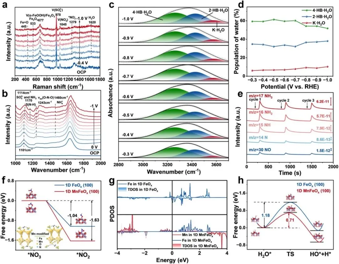
图4 (a) 不同电位下的原位拉曼光谱;(b) 不同电位下的原位ATR-FTIR光谱;(c) 表面界面水O-H伸缩振动的原位ATR-FTIR光谱;(d) 基于原位ATR-FTIR测得的表面界面水种群随电位变化;(e) 电催化NO₃⁻RR的原位DEMS测量;(f) NO₃⁻RR决速步的吸附能;(g) Fe与Mn轨道的PDOS profiles;(h) H₂O的吸附能Figure 4 (a) In situ Raman spectra of 1D MnFeOₓ at different potentials. (b) In situ ATR-FTIR spectra of 1D MnFeOₓ at different potentials. (c) In situ ATR-FTIR spectra of the O-H stretching mode of interfacial water on the 1D MnFeOₓ surface. (d) The potential-dependent population of interfacial water measured by in situ ATR-FTIR spectroscopy on 1D MnFeOₓ surface. (e) In situ DEMS measurements of electrocatalytic NO₃⁻RR over 1D MnFeOₓ. (f) The adsorption energy of the rate-determining step of NO₃⁻RR on 1D MnFeOₓ and 1D FeOₓ. (g) PDOS profiles of Fe and Mn orbitals in 1D MnFeOₓ and 1D FeOₓ. (h) The adsorption energy of H₂O on 1D MnFeOₓ and 1D FeOₓ.
图4 通过多种原位谱学与理论计算阐明反应路径与微观机制。原位拉曼与FTIR捕捉到*NO₂、*NO、*NH₂等关键中间体,并确认O-H键活化增强促进水解离。DEMS实时检测到NH₃为主要气相产物,且其信号强度在1D MnFeOₓ上比1D FeOₓ高近3倍。DFT计算显示,Mn掺杂使决速步(NO₃⁻→NO₂⁻)自由能降低1.63 eV,且Mn位点水解离能垒仅为0.71 eV(远低于Fe位点的1.18 eV)。PDOS分析证实Fe→Mn电子转移稳定高价Fe,促进FeOOH形成。该图完整构建了“Mn助水解离→Fe活化硝酸根→局部碱抑HER→协同加速还原”的反应全景。
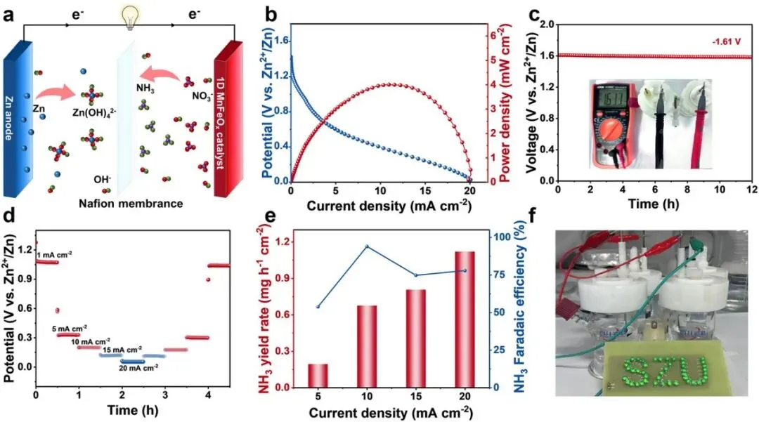
图5 (a) Zn-NO₃⁻电池结构示意图;(b) 放电性能与对应功率密度曲线;(c) 1D MnFeOₓ基Zn-NO₃⁻电池的开路电压;(d) 不同电流密度下的恒流放电曲线;(e) 1D MnFeOₓ在不同电流密度下的NH₃产率与FE;(f) 由两节1D MnFeOₓ基Zn-NO₃⁻电池串联供电的灯泡照片
Figure 5 (a) Schematic diagram. (b) Discharge performance and corresponding power density. (c) The open circuit voltage of 1D MnFeOₓ-based Zn-NO₃⁻ battery. (d) Constant-current discharge profiles of based Zn-NO₃⁻ battery at various specified current densities. (e) NH₃ yield rate and FE at different current densities of 1D MnFeOₓ. (f) Photograph of bulbs powered by two 1D MnFeOₓ-based Zn-NO₃⁻ batteries.
图5 展示了该催化剂在实际器件中的应用潜力。构建的Zn-NO₃⁻电池以1D MnFeOₓ为阴极、锌片为阳极,开路电压达1.61 V并稳定超10小时。在10 mA cm⁻²电流密度下,NH₃法拉第效率仍高达93.9%,产率0.68 mg h⁻¹ cm⁻²。放电曲线显示其在宽电流范围内(1–20 mA cm⁻²)均保持平稳电压输出。两节电池串联即可驱动LED灯板发光,直观验证了其“发电+除污+产氨”三位一体的实用价值,为未来分布式水处理与能源回收系统提供原型方案。